Saturday, 4 January 2014
Tuesday, 31 December 2013
Rewriting sidecar2 - much better JTAG speed now
One of the key features of my FPGA board is the coprocessor - an Atmel ATmega32u2 running code I'd codenamed "sidecar". This is responsible for the USB interface to the PC and disk emulation.
Up until this point, my USB code was quite hacky - based on the LUFA example USBtoSerial example, it had a USB-serial bridge and also allowed JTAG operations using USB control messages. Unfortunately, the chip I'd chosen only supports a maximum of 4 endpoints and a virtual serial port requires 3 endpoints itself (actually, the FTDI chip only uses 2, but it consequently needs a driver as it's not a standard USB CDC device) and so there was little choice in the matter. And control messages seemed to work for the most part, but I'd often get random disconnects whilst programming the flash chip (originally, it was about 1 failure every 5 flash cycles so I wasn't too worried). As the code I was running on the Atmel was getting more and more complicated (it also handles FDC emulation and the SD card), this failure rate increased to the point where the majority of reflash cycles were failing.
So, this was annoying and I was also getting fairly poor performance from my JTAG interface - it'd take about 20 seconds to flash the PROM for instance, which for a 200KB file is pretty slow! In the mean time, I'd decided to research booting the FPGA over JTAG as then at least I wouldn't be pummelling the PROM with all these erase-write cycles.
So, you know from the previous post, I've had a lot of difficulty with this, ultimately it turns out that contrary to the Xilinx docs, JTAG mode isn't always available and as soon as you start configuring the chip, it resamples M0,M1,M2 and reads data from there (although unreliably as it seems to use the JTAG TCK as it's sample clock, but it's still feeding the PROM CCLK at a much faster rate). So, I hooked up a spare data pin from the Atmel to the M0 and M2 pads (which fortunately, I'd had the presence of mind to bring out to a jumper as I'd always planned to support JTAG boot). This didn't work either.
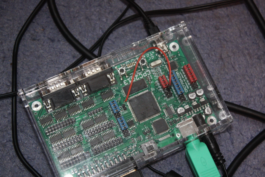
By chance I re-read the documentation and realised this pin was actually 2.5V level and so feeding it 3.3V from the Atmel, whilst not damaging the chip (fortunately) was causing erratic behaviour. I discovered that if I left the pins floating (I'd previously been pulling them to GND for PROM boot) then JTAG boot worked as the Xilinx chip actually contains pull-ups for these configuration pins. So far so good. However, I actually want the default option to be PROM boot and the Atmel takes a little time on boot before it can pull this pin low, so now the FPGA remains stubbonly uninitialised on power on. I tried having a pull-down resistor on these pins, but they fought with the pull-ups and put the voltage into the "not quite high, not quite low" territory, and whilst I could probably have won the battle by using a really low resistance pull-down, I didn't want the current loss when the Atmel was driving this high...
Despite all this, even though I could now boot via JTAG, this process was still unreliable - the USB stack was still crashing randomly, and so the whole thing was really frustrating. I got so annoyed, I kind of ignored the project until this week of holiday over Christmas. I'd wanted to do the USB stuff by interrupt, but the LUFA docs specifically mention how support for this was removed and how polling was the only option. However, my curiousity was piqued when I found Jim Paris' source for lufa-ftdi which emulates the functionality of an FTDI 2-endpoint serial port and does so solely through interrupts. I took a look, learned a lot more about the Atmel USB stack and started rewriting my sidecar code in a similar way.
So now, I have a rock solid JTAG implementation using 2 endpoints and because the whole process is optimised to use ping-pong buffers, it means I can do a 128-bit JTAG exchange per USB packet. Because these are bulk endpoints too, there can be more than one in a 1ms period, and because I'm using ping-pong buffers, I can be reading from a receive buffer (OUT), bit-banging the JTAG exchanging and writing to the transmit buffer (IN), whilst the PC is still reading the previous result (IN) buffer. Pretty sweet. Now, I can write the PROM in 8 seconds and what's more, the JTAG boot works reliably and boots in under 5 seconds.
I'm probably going to drop the serial port functionality, just because serial ports weren't really all that common on the CPC anyway, and I'm exploring the possibility of reconfiguring the USART into SPI-master mode and doing 8-bits of JTAG exchange that way instead which would further increase the speed.
Another casualty of this rewrite is that I've lost all my old FDC emulation and FAT code. The FDC code needed rewriting as its state machine was pretty buggy, but this is the next thing on the horizon now... :)
Monday, 25 November 2013
Booting an FPGA image over JTAG
I've been trying to get this working all weekend without success. It's incredibly frustrating as so many things seem to be "almost working" - after loading an image via JTAG, I can probe the USERCODE and even interact with my own BSCAN device and it seems to work, but seemingly everything else is inoperative, so no video out etc seemingly no activity on the IO pins...
Today, I just found this wonderful snippet via here:
So, it seems that the only way to get this to work is to not drive the M0, M2 high. Fortunately, my latest board I was contemplating driving it only by JTAG and so M2 and M0 are brought out to a single jumper, so the boot modes can be either "000" or "101". I guess I could expose this to a pin on the Atmega in a future board... :)Explanation of the problem:
The problem is that iMPACT causes the mode pins to be sampled. If the device is in master mode, the CCLK is produced and the PROM begins to load the device with data. This occurs before iMPACT issues the instruction to begin configuration. When this happens, the JTAG logic gains control over the configuration logic and loads the device with the bitstream. The fabric of the Spartan-3/-3E FPGA must be initialized before it can be written over, so frames that have been written to by the PROM will not configure correctly. The CRC check passes as this occurs, while data is passed into the device. The device goes through the start-up sequence, DONE goes High, and the device becomes operational. The problem is that the first few frames of the device have been corrupted and the design might not work successfully, and a verify with iMPACT fails.Work-around
Erase the flash or change the Mode pins to JTAG to work around this issue.
Wednesday, 11 September 2013
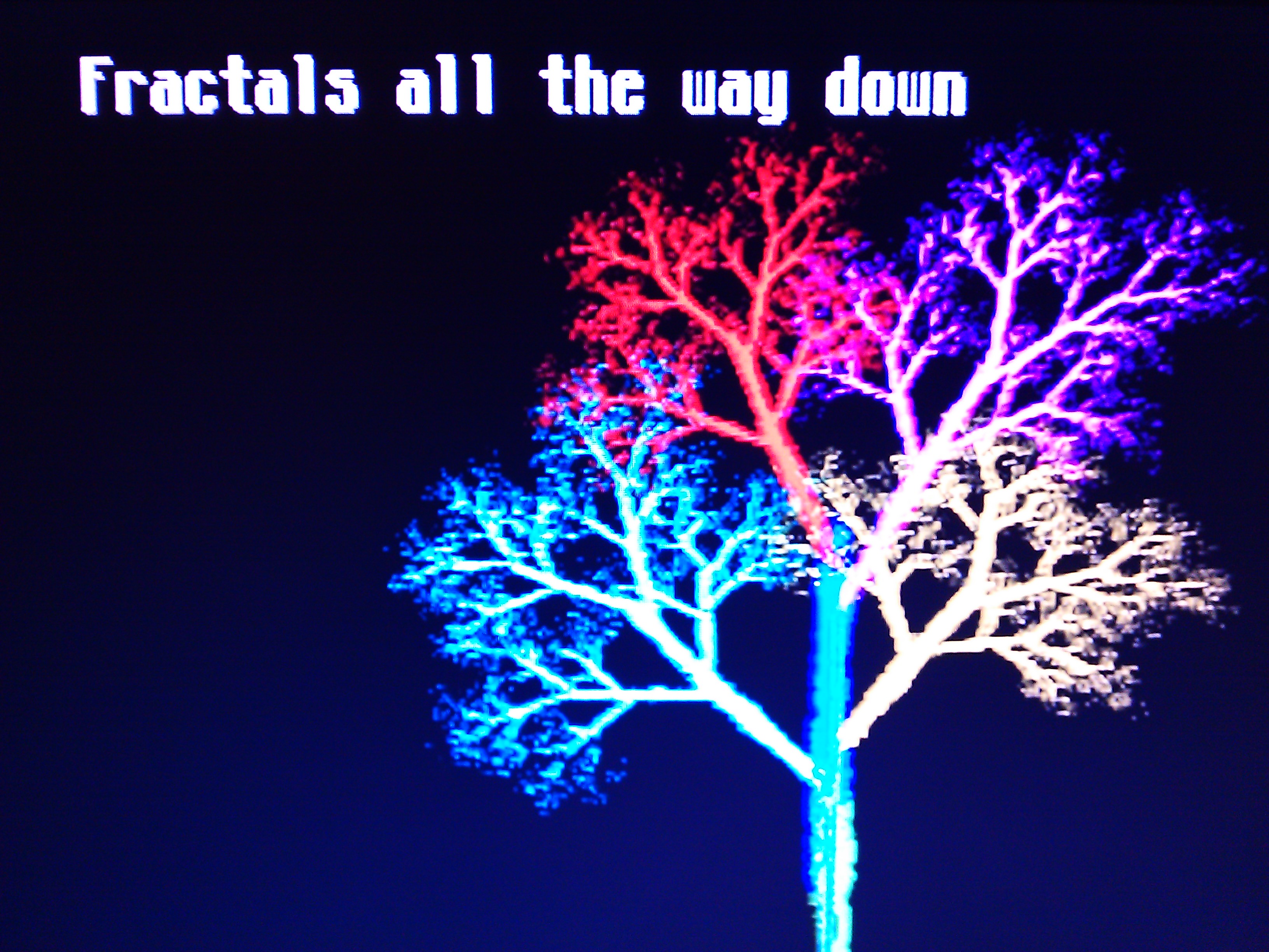
Fractals all the way down
"Fractals all the way down" came 2nd in the Wild compo at Sundown 2013. The pouët page for the demo is here.
Sunday, 8 September 2013
FPGA demo at Sundown 2013
So, I took a bit of a break from my Amstrad CPC core and made an FPGA only demo for the CPC2013 board. I haven't sorted out a video capture yet, but here's a little picture:
Saturday, 3 August 2013
Slow news month(s)
So, not much visible progress has been made over the last couple of months...
The laser cut case from the last video fit pretty well, as you can see them here:
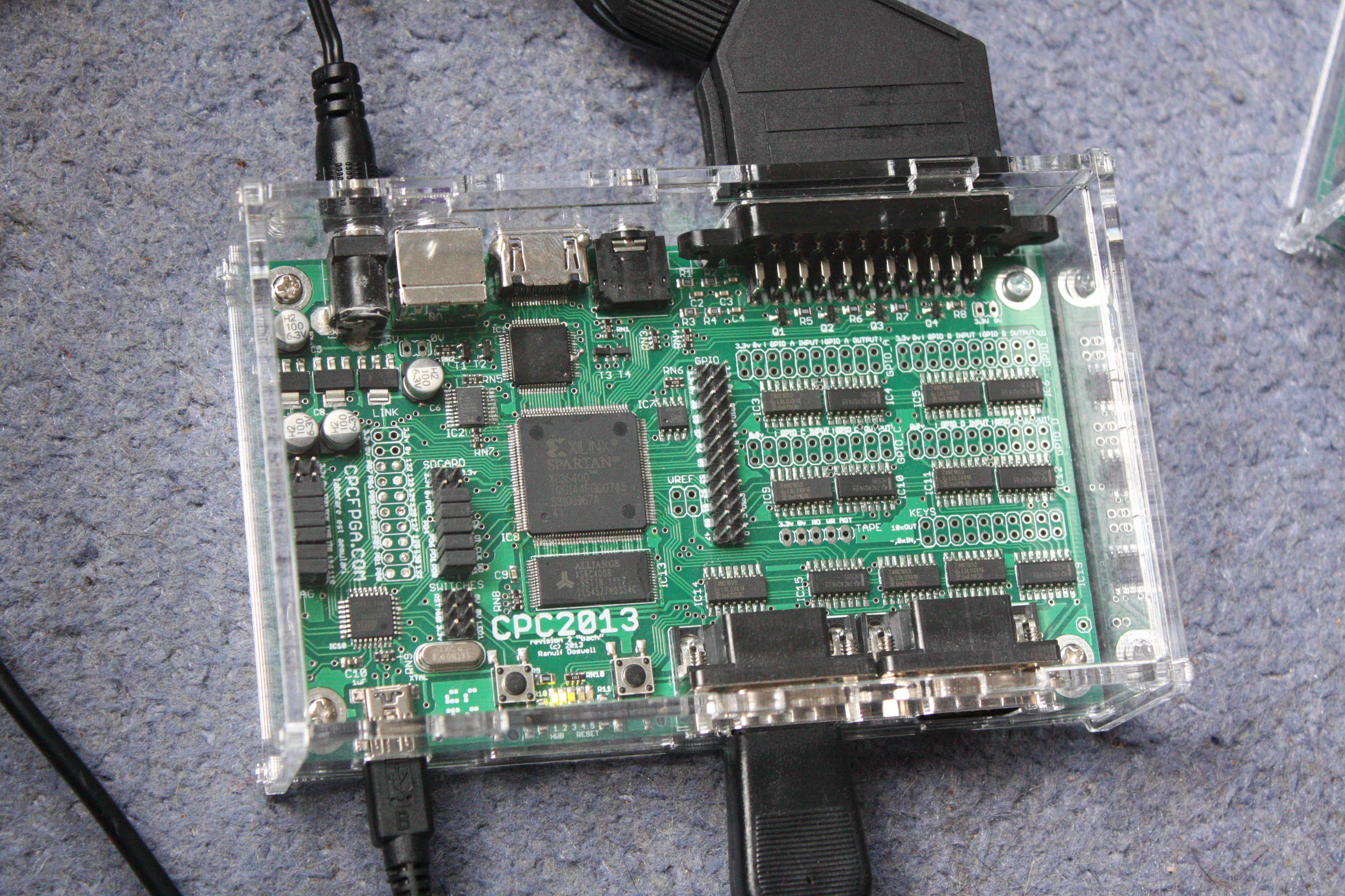

I would like to tighten up the holes a little so that the board doesn't rattle around when the PCB doesn't have feet attached, but it's still a pretty good second effort. Sadly, it looks like I won't be making any more cases for a while - fizzpop moved to their own building, so no longer has access to the laser cutter I used before. There are plans to buy one in the near future, but that'll be a few months off. And besides, I seem to be too busy doing other things to actually make it along anyway!
I've been (silently) working on the FDC emulation (which I decided to do on the Atmega side) - a first version works, but it's a bit buggy. It manages to load a few demos, but it's nowhere near stable enough to release publically.
I've also been trying to get the DVI transmitter chip to work. It looks like I forgot a couple of connections to the chip, although often fixing them up I still can't get the chip to actually transmit any data. It's hard to tell where the problem lies, sadly, so it might still be some time before I get DVI output working...
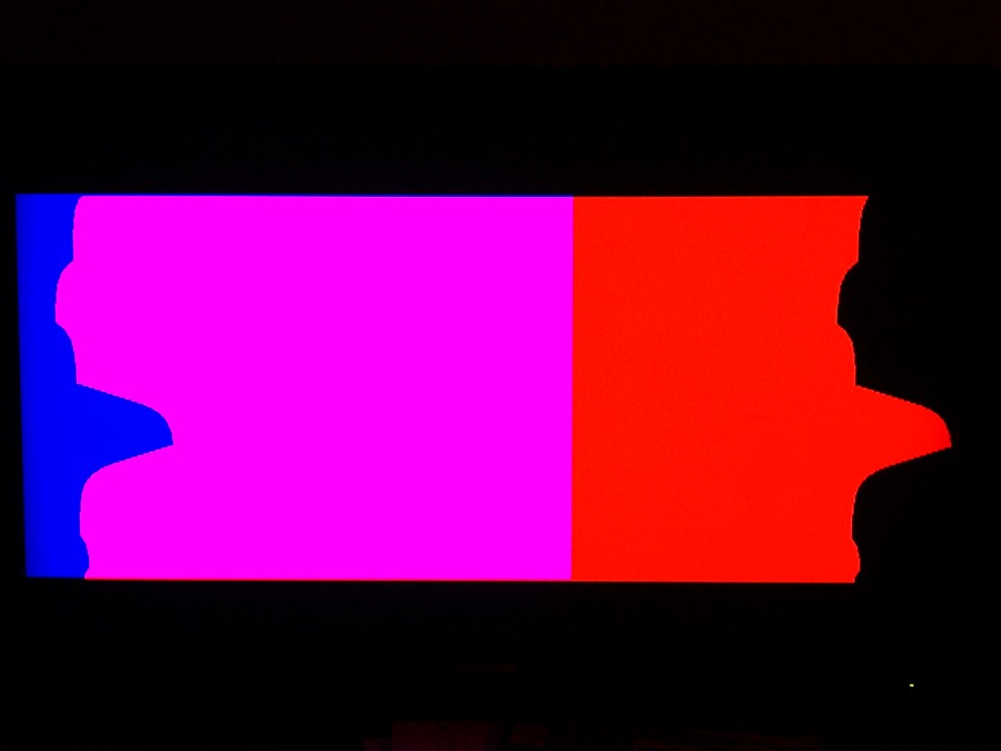
So today, I decided to investigate how many shades I can coax my 2-bit DACs to produce... I'll give you a clue, it's more than 4! :) There are about 30, although quite a lot of them are difficult to discern, but it looks like there are enough shades to produce the equivalent of a 4-bit DAC. I took some pictures so I can analyse them better:


The other big news is that I've got a new job, starting in 2 weeks. I guess that might mean I get even more busy though...
Thursday, 23 May 2013
Laser cutting a new case and other news
I've mostly spent the last couple of weeks making a start on the floppy disk emulation code. I decided to move most of the complex code that dealt with the FAT filesystem away from the FPGA as the state machine was getting very large and consuming lots of resources, and instead having it running on the Atmega support processor (which is fine because it's mostly idle unless being used as a USB to FPGA bridge and I've got about 14KB of flash ROM unused).
I've now fully encapuslated the IO between the two sides with a nice reliable protocol based on SPI where the different sides switch between being master and slave so that the AVR can be woken up by interrupt when the disk starts being used but then gain control so it's can manage the data transfer so that no bytes get dropped (as they might if the FPGA was the SPI master). So, now, I have the FPGA-AVR communication code working, the AVR handling the FAT meta data, so I just need to stick the disk image format code in... :)
And tonight, I was back at fizzpop after a couple of weeks of not being able to make it along. Here's a video of me cutting a redesigned version of the case to hold the CPC2013 board:
It seems that the holes are almost in the right place this time - I'll post pictures in the morning, but the acrylic is currently out in the porch until the smell dissipates a bit...
Subscribe to:
Posts (Atom)